So I ordered this forever ago and just got it, but I was unaware this was something I have to build. Looking at whats in the kit.. Do I have to buy additional components or was everything supposed to be included because there is definitely not everything I needed in here. also is there a detailed installation manual other than just the electronics diagram. And lastly whats the rod thing is it safe?
Hi EJ:
I just received mine as well, and there has been some postings for the parts. The main kit page (message 2901) has links to the BOM and Schematic, as well as firmware source code. The link to a short manual is there too but needs a correction, I think (leads nowhere for me).
From another discussion thread, member lolwut82 made a google docs spreadsheet with links to Mouser.de for European users (thanks for that):
https://docs.google.com/spreadsheets/d/1ceJ8O9P2hbkoHjhze52GsHzFghpHT7pXXaDxP0MvOd4/edit?usp=sharing
I edited the links to point to Mouser.com for North America or anyone preferring English, and posted that version here:
https://docs.google.com/spreadsheets/d/1bmanqcJtYQqQD-c1ioGJWCv2C7p6hMPfU3XaZmIHIJw/edit?usp=sharing
I also changed 2 links to what appear to be proper parts according to the BOM (Row 8 and row 22).
--Norbert
____________

I should have checked lolwut82's spreadsheet before posting; it has since been updated (thank you for that).
--Norbert
____________
I just completed my Mouser order, and I found some more link corrections.
CON1 linked to a 2 position header, we want a 4 position one.
CON2 linked to a 2 x 1 position header, we want 2 x 3.
I updated the English list: https://docs.google.com/spreadsheets/d/1bmanqcJtYQqQD-c1ioGJWCv2C7p6hMPfU3XaZmIHIJw/edit?usp=sharing
--Norbert
Re. EJ's last question - the "rod thing" is the Geiger-Muller tube, and yes, it's safe ;-)
I've just about got mine all put together but am a bit annoyed at the moment because the first display I had was too big for the supplied box, so I ordered a second one, and was just about to solder it in today when I noticed it's a parallel interface, not the I2C serial one, so I'm going to have to track down and buy a THIRD display (well, two actually, because I'm making up a kit for Euphoriabuzz as well).
When I get this thing finished and working, I'll post a list of the (correct) bits I bought and where to get them for users in the UK, and may offer to build them for other UK people too, if these two go ok.
So nearly there! Aaaargh! Right, back to eBay to see if I can find a display with the right bloody interface...
Regards,
Gary.
ps - I didn't find any instruction manual either, I'm just working from the circuit diagram and parts list.
I did not find a suitable display for the kit, that I'm sure will work....
( I used the Mouser part suplies for the other parts ).
I guess that the kit will work without the display, but - it's easier to find any errors if we got it up and running - or not :P )
Any ideas where to buy the correct display parts?
Regards Asbjorn - in Norway
____________
From Floroe, westmost city in Norway.
I also participate at Blitzortung Lightening detectors
My website
Have a nice day !
I've ordered this display :
http://www.ebay.co.uk/itm/140893044510
It looks like it's a standard display with a little board soldered underneath to the 16-pin parallel interface to handle the serial I2C input via its 4 pins (two for power supply, plus the clock & data lines). I intend to unsolder the interface board & remount that in the battery compartment of the case, with a 4-way ribbon cable to the DISP1 connector point on the kit board, then the display can sit on the two standoffs as intended.
Yes, I know the interface can probably be bought separately, but I couldn't find any and this was fairly cheap for the display AND board together.
By the way, I don't know if others had the same problem, but the supplied coil L3 was slightly too tall and prevented the display fitting on the standoffs, I had to unsolder it & remount it horizontally with extended pins soldered on. The electrolytic capacitors I've also mounted bent over at 90 degrees so I can fit slightly taller ones in ok without any clearance issues.
My new displays should be arriving on Wednesday. I'll let you know if they work and post photos.
Gary.
I did some display research as well, results in the 'News' message board. I think moving the interface board might be difficult, as the parallel display needs all the parallel connections as well (another ribbon). The active parallel pins that connect with PCB traces will have to be isolated by cutting the traces. I think the designer intended the interface board to stay under the LCD, as there is a screwdriver hole for contrast adjustment. Maybe 2 more standoffs on the LCD just resting on the PCB edge will be sufficient support instead of the header.
For the too-tall L3, I cut the heatshrink off the top with an Exacto knife, it's exactly 10mm high then.
____________
Success! There was no cutting of traces involved, and the display I ordered as in my previous post is just attached to the display pcb by pins through the 16-way parallel conector along one edge. All I did was separate it (tried unsoldering, but that was proving difficult as the pins are quite well soldered through both boards, so I just cut through the connecting pins carefully with a hacksaw and cleaned them up, then soldered my ribbon cables onto the exposed pins. Relocated the little adapter board into the battery compartment, used an 8-way ribbon for the data pins, 2 for the contrast backlight and 6-way for the remainder, so all 16 pins reconnected, plus the four way to the VCC, GND, SCL & SDA input from either DISP1 or DISP2 connectors (they're both wired to the same places, so either will work). I've taken some photos, will sort out my list of components too & add these later. It works at last! Woo-hoo! :-)
I become a little bit tired here :-p
There are 3-4 discussions about the new kit in in all different categories.
Maybe this forum have any sort of admin who can clear this up.
Maybe here is any admin who can tell us DEFINITELY what we have to order to get this sensor working.
Maybe here is any admin who can post a how-to with some pictures.
Solder is NOT my daily work.
We have here questions over questions but no answers from project manager...
:(
I hear you Chris. The admins appear too busy to regularly participate on the forum, but they do respond to private messages on occasion. I think 'Science' is the most appropriate board to use for the kit assembly discussion, so my suggestion is to keep it here. I'm still waiting for my E-Bay serial LCD with expander board, but I think the method below will work without needing long ribbon cables. BTW, congratulations Gary for being the first to get this display working.
Use IC socket strip pieces on the main PCB to create a low profile 16 pin female header. If the LCD/expander you get has pins, see that they insert and stand off by 10mm (to make the case close properly over the LCD). If there are no pins, use 12 clipped LED leads (they are stiffer than resistor leads) to make pins of the proper length, from the LCD through the expander to the socket strip. On the main PCB, DO NOT install 2 of the jumpers (the long one just above the 16 pin header, and the short one connecting IC1 pin1) - these would interfere with the display parallel pins. Also don't use long pins on 7, 8, 12 and 13, as they too would interfere with the display parallel connections. And of course leave out VR1. That leaves 12 pins to hold the display, provide extra power/gnd connections and connect the LED backlight. Short wires and a female connector for the 4 side pins make this LCD fully removable.
--Norbert
 krzyszp
Project administrator
Project developer
Project tester
Project scientist
Send message
Joined: 16 Apr 11
Posts: 383
Credit: 825,912
RAC: 0
I become a little bit tired here :-p
There are 3-4 discussions about the new kit in in all different categories.
Maybe this forum have any sort of admin who can clear this up.
Maybe here is any admin who can tell us DEFINITELY what we have to order to get this sensor working.
Maybe here is any admin who can post a how-to with some pictures.
Solder is NOT my daily work.
We have here questions over questions but no answers from project manager...
:(
As far as I know, Szopler had published list of required parts on his KIT topic long time ago...
BOINC server forum gives very little administration functionality...
KIT's are for people who more or less are prepared for soldering and mostly know how to read diagrams and kind of manual published by Szopler (i.e. I don't know, and I'm not order it even if I'm really interested in this version - as on all versions, because I'm in project from day one)...
Apologise if I'm to offensive but really I think that KIT's are for more advanced users...
____________
Regards,
Krzysztof 'krzyszp' Piszczek
Android Radioactive@Home Map
Android Radioactive@Home Map - donated
My Workplace
My kit is working mostly, but has a USB problem. I'm still waiting for the proper display, but it clearly detects ionizing radiation (clicks at the expected rate), and the right button cycles through the 4 modes (LED only, nothing, beep only, and beep+LED). Has anyone gotten their 2.61 kit fully functional and on the map? If I can't solve the USB issue, I hope I can use the RS232 serial data to participate.
--Norbert
Have now get the current 2.61 sensor completely and on map (ID 14139). On Windows, I had no problems. In Linux using the Raspberry it was difficult there, he had to be entered via console.
I've got my v2.61 kit working with Linux now (Mint 17.1), and Euphoriabuzz has one running fine with Windows 7. Norbert - double-check you've got the zener diodes DZ2 & 3 the right way round. DZ2 has the black bar end furthest away from IC1 (opposite way round to DZ1 which it is right next to), and DZ3 is behind the USB socket with its black bar end furthest away from the RS232 connectors. Also double-check with a multimeter that none of the solder on the 5 USB connector pins has bridged across to any of the other tracks - they're very close together on the board there. I'm assuming you did spot the wire link next to DZ3 as well. Hope you get yours working soon, it's interesting to hear how others have built their kits. There are some photos of my kit being built on here :
http://freespace.virgin.net/gaz_liz.teamamc/RK261HTG/Radkit261.htm
Thanks, Gary for the suggestions; they all check out; I want to see what comes from the serial port and LCD before proceeding (still waiting for the inverting RS232 adapter and I2C display). If they don't point to the problem I have to either try to access the firmware via the ISP port or find a USB tool that gives more info than the OS (Windows "Code 43" can mean just about anything apparently).
I don't know if the serial data can be used to feed the project; I trust Szopler can clarify.
--Norbert
http://www.mouser.com/ProjectManager/ProjectDetail.aspx?AccessID=c37492dd34
Is this now the right list i have to order ???
I understand with this parts i can complete the sensor without display but working ???
____________

That list has the wrong number of positions for the first part (CON1), has radial inductors, etc. so it looks like the older list. I can vouch for the spreadsheet I posted that has updated Mouser links. I tried previously to edit this ProjectManager list but could not, hence the google docs spreadsheet:
https://docs.google.com/spreadsheets/d/1bmanqcJtYQqQD-c1ioGJWCv2C7p6hMPfU3XaZmIHIJw/edit?usp=sharing
The right side shows all the changes from the early parts list. If you don't want the display, then you can delete the 3 associated components. This will allow the kit to work with the project.
--Norbert
i miss C12.. ceramic capacitor... is it the same as C9 ?
Also i find a very small capacitor in the Kit... i don't know witch component it is...
____________
Chris, C12 is 22pF but doesn't need to be rated at 500V (or higher) like C9 does. You can use a high voltage one for C12 if you have one handy and it fits, it doesn't matter, as long as it is 22pF capacitance value.
The small capacitor in the kit is C11, 4.7nF.
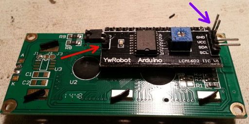
Well, I finally got a proper I2C display, and I made it fit. It came with the interface board already attached, so I didn't try to solder in long mounting pins like I had planned. To make it fit, I had to remove the LED jumper (red arrow) and replace it with a solder bridge, and bend the I2C pins straight (purple arrow, half are done):
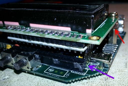
This now fit OK but not perfectly. The display still sits ~3 mm high, requiring spacer nuts and longer M2.5 screws (red arrow below). The contrast trimmer is offset from the PCB hole but a small screwdriver on an angle worked. I soldered the straightened pins directly to the PCB (purple arrow), but I should have made another IC socket header strip and trimmed the 4 pins to fit into the socket. I ended up not using the 16 pin IC socket header that is in the foreground:
With the higher display I had to trim the hole in the case, which was not fun. I used small wire cutters and a file to do this. I also had to file the 3 small holes to make the buttons operate easily. Overall though,I think it looks good enough.
Due to the variation in interface boards, I hope the next design (if there is one) specifies *exactly* the display models required for each option, or if not, leaves more space.
Hmmm, i guess i miss C19 Resistor 33k ?? There were one in the Kit but i need 2 ???
GGrrr....
Half the way now...

____________
Looking good so far Chris. Yes, I only had one of the 33k resistors too, looks like this is the same for all of us then!
Norbert - I think your box looks quite good with the display raised up higher, but yes, it must have taken a lot of time to carefully file the hole bigger to make it look as neat as that. Good effort!
Chris,
are you sure your C9 is a 500V type? It doesn't look like one.
Regards
Holger
They told me here C9 is same as C12 ... 500V not necessary... ?? See Message 3088.
I ordered now all parts from 2 distributors... incl. shipping costs around € 50,-- and now i miss a resistor 33k that have to be in the kit.... i'm not lucky with this !!!
One more question... the cable from tube to massa.. how thick it must be ?
____________
Hi Chris, I think you've misunderstood what I put in message 3089, C12 doesn't need to be high voltage, but C9 does. I would recommend a high voltage capacitor for C9.
The cable for the other end of the tube to massa (ground) can just be a thin one, there is negligible current flowing through it. Any plastic coated connecting wire which fits in the hole on the pcb will be ok.
Sorry if I confused you with my earlier post. I think what I said is correct, but may have worded it badly?
Gary.
ps - just sent you a private message Chris :-)
hmmm in the Google doc above i find for C9 this link... http://www.mouser.de/ProductDetail/Murata/DEA1X3F150JP3A/?qs=%2fha2pyFadujcxkB4SX7j71HXiiD6%2fG0f%252bU6Sz2%2fOlM6k63mbo5vBig%3d%3d
but this is 15pF
Sorry i don't know what i have to order...
____________
Holger Weiss has posted a BOM on another thread which has a better capacitor for C9 (22pF, 1kV) :
http://radioactiveathome.org/boinc/forum_thread.php?id=475
The standard little brown disc capacitors are only usually rated at 100V (though some can be higher). The GM tube in the kit operates at more than this (about 400V?) so C9 needs to be rated at more than 400V really, say 500V or 1kV are the usual values you'll find, or it won't last very long.
Hi Chris,
C8 & C15 seems to be soldered in the wrong direction. The white line on the Elko is Minus ;)
Yes Dark Soul... i recognise that already :-P
Good eyes you have :D
____________
I finally received the USB-TTL converter to read the RS-232 port data from the sensor, and it sends a 3 or 4 byte ASCII string every second with the ASCII value of the display number in hundredths of a uSv/h. That is, if the display shows 0.08 uSv/h, the ASCII string is ASCII 8 then <CR><LF>. In Hex, it is 38 0D 0F.
This confirms that my sensor is communicating data OK on RS-232 so the firmware seems to be OK. The USB still fails to enumerate so I have to conclude that one of the USB pins is bad on the AVR chip. I don't know if this serial data is useable by the project. I'll send another PM on this.
Well, I can't seem to get a replacement AVR chip and the serial data from the V2.61 kit is apparently not useable by Radioactive@home, but at least I'm on the map (the RadMon.org map). I was very happy to find that their RadLog Lite software reads the serial RS232 data from this kit, using a TTL - USB converter. I foam taped it in the battery area and soldered the +5V, Gnd and RXD wires. I cut away some of the case to allow the USB female 'extension cord' to fit.
 .
.
The converter is this one http://www.ebay.com/itm/New-PL2303-USB-To-RS232-TTL-Converter-Adapter-Module-/130682850512?ssPageName=ADME:L:OU:CA:3160. The RadLog software only needs the Com port created by the TTL - USB converter, and a conversion factor uSv/hr of 0.01 (and no need for BOINC).
Hello again... after 6 weeks waiting i finally got the display.
But now... i see 0.00 uSv/h and the buzzer is beeping non stop.
First unit:
core_client_version>7.4.42</core_client_version
Radac $Rev: 585 $ starting...
sensors.xml: 7 nodes found
Found sensor [unknown version 609 (2,61)]
553590,0,2015-4-22 17:3:39,f,9.2 minutes,0.0 cpm,0.00 uSv/h
793973,0,2015-4-22 17:7:39,n,4.0 minutes,0.0 cpm,0.00 uSv/h
1034125,0,2015-4-22 17:11:39,n,4.0 minutes,0.0 cpm,0.00 uSv/h
1274365,0,2015-4-22 17:15:39,n,4.0 minutes,0.0 cpm,0.00 uSv/h
1514401,0,2015-4-22 17:19:39,n,4.0 minutes,0.0 cpm,0.00 uSv/h
1753682,0,2015-4-22 17:23:39,n,4.0 minutes,0.0 cpm,0.00 uSv/h
1993907,0,2015-4-22 17:27:39,n,4.0 minutes,0.0 cpm,0.00 uSv/h
Trickle sent
2234318,0,2015-4-22 17:31:39,n,4.0 minutes,0.0 cpm,0.00 uSv/h
Trickle sent
WARNING: No readings from GM tube !
Done - calling boinc_finish()
19:31:39 (8576): called boinc_finish
____________
Unplug sensor & remove the GM tube, check for short circuit with a resistance meter, should be open circuit (very high resistance). If ok, replace & plug sensor in. Put a voltmeter across the GM tube - what voltage are you getting there? (should be a couple of hundred volts) If that's ok, time to post some photos on here & see if anyone can spot anything wrong?
i have 190 Volts at the tube. Foto's here: http://1drv.ms/1DJlGRp
I triple check the soldering... can't find anything.
The problem with the buzzer is solved.. is quiet now :) but still no readings from tube.
Resistance without tube is around 27 MOhm
____________
Is one end of your 33k resistor (R19) touching the metal spacer? Just push it away a little if it is, as the spacer is grounded.
You have good voltage at the GM tube, so it sounds like the pulses aren't getting to IC1. Check IC1 pin 14 is connected to IC2 pin 1 ok, and not grounded. Also check IC2 pins 2, 3, 5, 6 & 7, make sure none of those are grounded either. Only pin 4 should go to ground. It's easy to have a stray blob of solder connect to ground (or anywhere else), just a small bit you might not be able to see could short it and stop the pulse getting through. Check with resistance meter (while sensor is unplugged).
The solder-side closeup seems to show a cold solder joint for C6 next to IC1 pin 7, where it may not connect well to the PCB trace. To check for solder bridges, I find a good backlight is better than magnification, as the shiny solder and flux can play tricks on my eyes. The backlight shines through the PCB and the gaps are easy to check.
OK, after a short journey to GB my sensor arrived back and works fine :)
The only problem left is that i can't see it at the map.
I set the location and add the sensor, but it will not appear in the map yet.
Very special thanks to KarmannGaz; DarkSoul and --Norbert for the great support ;-)
____________
Glad you've got it back & running ok now! :-)
Now you are getting credits for your work units, you should just be able to move the marker on the map to where you want it, then click on "Add sensor", and that should be all there is to do. I wonder if there was a problem at the server end when you tried it - try again and see if it works now? I did notice my computer was unable to contact the Radioactive@home server last night for a while, maybe it was the same time as you tried to update your map position, may just have been unlucky timing.
I did several times... on my device page the point of location is correct... i click several times to add sensor... but nothing at the big map..
____________
Oooh, you've got one of your computers (13354) on the map! I see you've been having some fun aborting tasks on 14628, this sounds remarkably similar to a problem Euphoriabuzz had - http://radioactiveathome.org/boinc/forum_thread.php?id=474#3091 - not sure if that's any help?
At the first machine 4 units run without problems, but than a unit stacks... next one also... had some massages:
41661 Radioactive@Home 18.05.2015 17:48:49 [error] garbage_collect(); still have active task for acked result sample_4874361_0; state 5
41662 Radioactive@Home 18.05.2015 17:48:51 [error] garbage_collect(); still have active task for acked result sample_4874361_0; state 6
41673 Radioactive@Home 18.05.2015 18:15:57 [error] Couldn't delete file projects/radioactiveathome.org_boinc/radac_1.78_windows_intelx86.exe.gzt
Than i take the sensor to another machine.. where it runs now 16 hrs OK.
And this machine appears at the map also :D
So i think its fine now.
Thanks again.
____________
Finally got the last parts today, and buildt the kit.
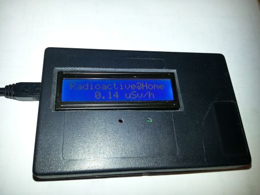
It is now running, and I currently have a reading of 0.09 µSv/h .
Installed the Boinc Radioactive@home project, and it's now running on
a PC that is also connected to Echolink (Amator Radio applicationthat controls
a radiostation).
The Boinc properties shows that my computer ID is 15215,
and my quiestion is ;
Is there something more to do ?
Or is the project running as it should be,
and my station will appear on the map ?
Regards Asbjorn
____________
From Floroe, westmost city in Norway.
I also participate at Blitzortung Lightening detectors
My website
Have a nice day !
Congrats :)
I think there is nothing more to do... your sensor is visible at the map :)
____________
Thanks ;)
Now I'd like to put some data on my website ...
I already have an lighteningdetector project going at aa-mot.net/mybo,
and a combination could be interesting, - thinking about the possibility of an radioactive burst caused by the lightning itself.
Anyway is there some place to find scripts or code that I could use on my site ?
Regards, Asbjørn.
By the way, there are 3 pushbuttons in the kit.
But either I'm blind , or there is no spec in what they do ?
( the search function on the forum did not give me an answer...)
Regards, Asbjørn.
The left button doesn't do anything yet, maybe for future use. The middle button controls the display on the sensor - you can have it on with backlight, on without backlight, or off. The right button controls the flashing LED and buzzer - you can have just the LED flashing (default), LED off, beeper on, both on, both off. Just keep pressing and it cycles through them (I may have got the sequence wrong, but you get the idea) :-)
ps - congratulations on getting your kit built and running, nice to see another one working! 8-)
Here you find some url for personal data:
http://radioactiveathome.org/boinc/forum_thread.php?id=485
____________
Thanks for the info !
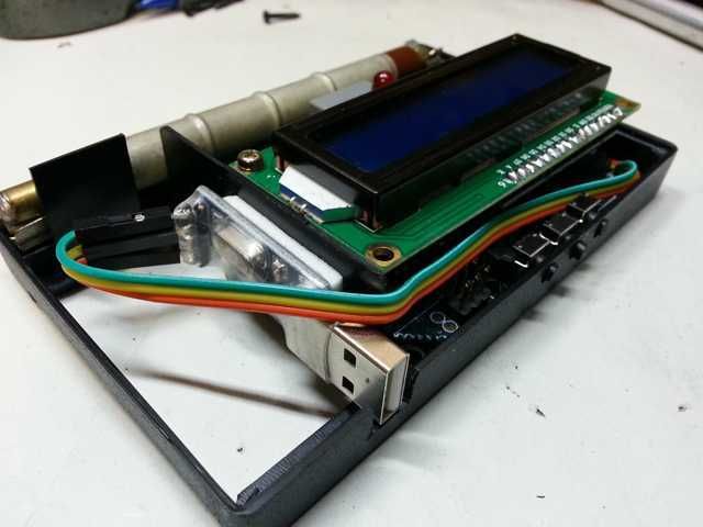
It's working good now, and the Display suggestion earlier in this thread,
was indeed a good one !
It fitted in just fine, ( mounted the kit yesterday), and the kit was running ok at first try.
I started the for the forst time with an batterypack for USB, to insure that it should'nt kill the USB connector at the PC.
After that everything worked as expected.
A comment though; the drawing of component placement on the board, was almost unreadable for some of the parts.
But skipping a few parts until I got the readables in place, it was a bit easier.
I suggest that one make a complete usermanual both for building the kit, images for component placement, and some security warnings about the high tension voltage.
Anyway, Its fun to get it up and running, after a long wait for the needed parts... !
Have a nice day !
Regards, Asbjørn