Hi,
i have a Detector V2.60 from the second pach.
Since one Month i get only 0,0 uSV on the Display.
The Geiger tube is connected but i cannot see any issue.
Finde attached pictures from the Kit.


thanks for your help
Werner

Is this one which was working ok up until a month ago but is now saying zero all the time, or have you only had it a month and it has always had zero on the display?
I suppose the first thing to check is with a voltmeter across the GM tube - are you getting a hight voltage there? Should be a couple of hundred volts, I'm not sure of the exact value because I don't have one of those kits, mine is v2.61 and it doesn't have the transformer for the high voltage part. If you are not getting high voltage at the tube, check for continuity of both coils of the transformer, and that they are soldered to the pcb ok. If the high voltage is ok, it could be the pulse counting part which is faulty. I think I saw a circuit diagram for it somewhere, I'll have a look if nobody has any better ideas, but check the above first.
Hi KarmannGaz,
my Detector have working 1 year without any trubbles but since one month i can see only 0,0 uSV on the Display.
I have a voltmeter but i dont know if i can check high voltage with my voltmeter.
Could you see on the pictuer if i can check high voltage?

thanks
Werner
Hi Werner:
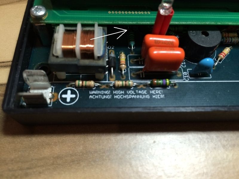
The highest voltage setting on your meter is 250 VDC. Turn the dial to the dark 250 where the V has a straight line under it (this means DC, Direct Current), not the wavy line (AC, Alternating Current). The proper tube voltage is near 400V, which is more than your meter will display, so DO NOT measure the tube directly (you may destroy your meter). The V2.60 kit has 2 resistors R15 and R16 that feed the high voltage back to the controller chip, and the point where these 2 resistors connect together is half the tube voltage. If you measure here with the red lead and with the black lead at ground (e.g. the clip end of the tube), you should see near 200V.
The clip end of the tube is positive I think, ground is the other end? However, that will still work, probe connected between those two resistors and either end of the tube should read about the same, just one way as a negative voltage and one way positive. I'll go along with what Norbert is saying :-)
Hi,
i have checked the platine but i cant find the R15 and R16 resistors.
Could you tell me how i should check the Voltage?
My voltmeter is only for max 250 Volts.

thanks Werner
KarmannGaz is right; the clip is positive not ground, and I agree it should not matter for this test. The reading will show as negative if your black lead goes here (switch the leads to get a positive reading). The resistors are the ones with brown, black, black, green, brown stripes. Put the other lead on one of the legs between them.
One thing I just noticed in your photo, though; the tube itself seems damaged. It looks a little bent and bulging in the middle, and there seems to be a tiny hole near the 'C'. If the gas inside the tube has leaked out, it's dead. If you get a voltage during the test, a new tube seems to be in order. Did the unit suffer some damage before it stopped working?
It could be the lighting, but that GM tube looks a bit dented to me? They are delicate, it could be broken? Did it get dropped just before it stopped working?
Anyway, R15 and R16 are almost underneath the GM tube near the positive clip end, you can just see one of them in the photo, between the orange capacitors and the transformer, the other one is hidden by the transformer. It looks like there's just enough room to get your multimeter probe onto the end of the resistor which you can see there. Put the red probe there, and the black one on the negative end of the tube, and you should see a high voltage on your meter (but below the 250V max so it should be ok).
I think it's R12 and R18 that are below the tube (I just made a correction in my post below). Actually, either resistor pair should work for this test, but It's hard to tell from the top photos which end of the tube-covered resistor is the correct one. I recommend between R15 and R16 as stated below.
Thanks Norbert, and sorry for repeating what you posted earlier, I hadn't spotted you'd already replied. Ignore my previous post, it's late and I need to go to bed! Just follow what Norbert said. We're both thinking the same thing though - I suspect the GM tube is dead.
Hi all,
thanks for the lot of answers.
The damage to the tube did not occur until after the failure.
I would like turn off with my fingers from the holder and i gripping in the middel of the tube, so i think that was not a good idea.


Whats your think should i try a mesure?
See for an example is the measurement so right?

The black pen is between the both resistors are the ones with brown, black, black, green, brown stripes.

Ah, yes, that's the right place to measure, however I think you could skip that now and just go buy a new tube as I'm pretty sure that's what's wrong.
There is another thing I was thinking too - if there is no current flowing through the tube, which is true most of the time even when it's working (it only passes current briefly each time the gas inside ionizes and you get the pulse), then there will be the full tube voltage right the way across both of those resistors anyway, you'll only get half voltage at that junction at the brief moment it pulses, and your meter might not be quick enough to detect it anyway, so I think it will show as too high voltage. That would be good though, even if you can't get an exact measurement, as long as it's showing high voltage detected, it would show it would work if you put a new tube in.
I wonder if you could put a small neon bulb (like out of an iron or night light) in place of the tube, if that would glow and show high voltage? Might be an easier (and safer) way to see if it's generating high voltage ok. I haven't tried it myself, it's just a thought. Anyone else agree?
Hi,
I get the Detector as assembled, so i dont know where i can order a new tube.
Does anyone know where I can re-order it?
thanks
Werner
Have a look on eBay for STS-5 or SBM-20 Geiger tube, there are several on there. Either of these will fit. While you're on there, it might be a good idea to buy some 20mm fuse holder clips and solder one to the wire at the negative end, so the tube will just clip in. It's not a good idea to solder directly to the tube.
Hi Werner,
I hope your new tube is on the way. You can still measure the voltage, though. The resistors your black probe touches in your photo are R12 and R18, the ones going to the tube, and as KarmanGaz says may change value depending on the tube state (without the tube they are likely 400V). If, on the other hand you measure between R15 and R16, it should be stable around 200V and safer for your meter. These are the resistors feeding the tube voltage back to the regulator circuit, and are the resistors with 2 black stripes (Brown, Black, Black, Green, Brown). See the white arrow in the photo.
P.S. There seems to have been a server problem for the past week or so. I'm glad it's finally back. Anyone know why?
Hi all,
I am back from our Holiday.
I have order today a new Tube.
I have messure with my voltmeter.

I have use the red stick from the voltmeter and go on the resistors where i have marked in red and the black stick i go to the tube.
I saw on the voltmeter a value of 406.
Voltmeter setting as follow.

thanks
Werner
Hi Werner:
That is not the right spot to measure at; the right spot is between the 2 bluish resistors. Look carefully at the white arrow in my post below where it's pointed. These 2 resistors have the correct stripe colors. Where you measured, the stripes are brown, orange, yellow, gold.
Hi Norbert,
thanks for your reply and your info.
I have now messure again but i get 0,0 Volt on the voltmeter.
Now how i can check witch part is defect?
I have written an email to Szopler 2 month ago for a maintenance but i dont get an answer.
Do you have any idea?
thanks
Werner
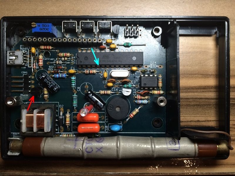
I don't have this version of the kit, but based on the schematic I would first check pin 5 with the volt meter (blue arrow), to see it it is sending pulses. The meter will only measure DC, but the value should be between 0 and 5, not 0 and not 5. The pin should be oscillating I think near 50% duty cycle (half on, half off), so near 2.5 V DC average. If this looks OK, then check the input side of the transformer, at pin 3. Now I can't see the pins on the other side of the transformer, but I see a "1" on the board, so it may be the third pin below that. At any rate, it's the pin that connects to the black half-circle device, transistor 3 (T3, red arrow). You can only be sure by seeing the trace on the bottom of the board. This pin should also be around half-way between 0 and 5V. If both are OK, the transformer is most likely broken. If the first reading is OK but not the second, T3 is likely broken. If both are bad, the main chip, IC1 is likely broken. If you are lucky, you may see a bad connection on the board near here, which can be fixed by soldering. By the way, it's standard practice to ensure the board is powered before making any other test measurements, such as pin 1 of the transformer must be 5 V, and also pin 7 if the main chip IC1.
--Norbert
I've just noticed something else too - to the right of C14, between the two ICs and below where it says DZ4 - there is a resistor which looks like it's broken in half? Difficult to see from the photo if it's broken or just two resistors in series to make up that one, but if it is broken, that won't be helping things and needs replacing.
Hello there,
@KarmannGaz: I have checked the resistor and i think that is normal. Two resistors is conected with solder (i hope this is the correct word)

So now i have make a messure again and i hope i maked correct.
First messure is Pin5 with transistor T3 and the resault was 004.

The next messure was Pin3 with transistor T1 and the resault was also 004.

I have turn off the Display so that i can make a better messure on the tube and the resistor. Now the resault is 204.

I have now realy an idea what i can do.
Only one think is i wait of my new tube is received and i could check is this the reason or not.
Or do you have any idea?
thanks
Werner
I think the circuit is good based on your 204 V reading. The measurement location of the probes means that the overall tube voltage is 408 V, which is what the tube needs. It should work with your new tube.
For future reference, all other voltage measurements mentioned should be made with the black probe at 0V or ground, and the red probe at each location. The black chip (IC) pins are numbered counter-clockwise with pin1 marked with a small indentation (lower left here). So on the big chip IC1, pin 5 is correctly shown by your green arrow below. But pin 3 would be to the left of that, and your red arrow points to pin 12.
Hi Norbert,
thanks for your info. I have now messure on the correct Pin3 and T1 transistor.
The resault is also 004.
The new Tube is maked as Shipped on 09.09.
Last Tracking was on 19.09, so i hope the Tube is comming soon.
I have read that i should not connect the new tube with a cable and solder directly. Do you know where i can order a clip for the tube?
A article number would be also helping.
thanks
Werner
Ah yes, the two little resistors together is ok, not broken then! :-)
Any 20mm clip should be ok, I used one like this :
http://www.ebay.de/itm/6-10-Sicherungs-halter-clip-f-Feinsicherung-5x20-M205-PCB-Mount-Fuse-Holder-/141759230039?var=&hash=item2101823057
then solder to the legs of the clip and trim them to fit in the case if required.
I think your new tube should work too, I agree with what Norbert said :-)
Hi all,
i get my new tube and the new clips. I have installed and make a test but i get always 0,0 uSV :-(
Now i have no idea what can now broken.
Ah :-(
So you still get 204V (or thereabouts) at the point you measured in the earlier photo above? (and probably across the tube as well, those multimeters will add a load to the circuit and read lower than the actual voltage anyway). If so, I'm not sure what to suggest next.
Does the underside of the circuit board look neat & well soldered? I'm guessing it will do, as the top looks very neat. I was just wondering if there are any dry joints there. Sometimes if a joint hasn't soldered very well, it can go "dry" after a while and not make the connection any more. You can sometimes fix these by just touching them again briefly with a hot soldering iron to re-melt the solder. May be worth a try if you can see any that look suspicious or any of the components move when they shouldn't. Don't overheat the legs of transistors or the ICs though, just a quick touch and let them cool quickly again.
Anyone else got any ideas?
It was working before, so it must be one of:
- new tube is installed backwards (Plus on the board, other end hanging out with loose wire attached)
- new tube is no good
- something else on the board is bad. As Karmanngaz says, look closely at the solder joints; maybe one came loose when the tube got damaged. Pay most attention to the area around IC1, the 8-pin chip. That is where the detector circuit is. I'm not sure how to reliably check the pulses coming out of pin 1 of that IC, they are likely very short so won't show up on a digital meter. This is where the old needle type meters are better (you would see a little jump on the needle every time the tube fires). Hmm, you can also measure the resistances using your multimeter on the ohms scale (the omega part at the dial's top left). Use the setting appropriate for each resistor value and google 'resistor color code' to read the bands. The readings should never be higher than the resistor value (within 5%), but can be lower due to other components in the circuit.
Hang on a sec. Where is DZ4? There's nothing there in the photo. I believe it is necessary to protect IC1 from high voltage spikes when the tube fires. Was it really working before without this? In any case, it's possible that IC1 is now damaged. I would buy a replacement DZ4, IC1 and any resistor that is way over it's proper value. Solder in DZ4 and any bad resistor, then see if it works. If not, clip all the leads of IC1, de-solder the 8 pins still in the holes, and solder in the new IC1.
DZ4 is probably in the backside due to a problem with the design of this board. See here
http://radioactiveathome.org/boinc/forum_thread.php?id=219&nowrap=true#2596
I would test R12 and R18 (the two 5.1 MOhm under the tube) because they should be 0.6 W resistors and seems they are 1/4 W instead
____________
my backside is clear but on the front side i have two orange resistors (C10, C13).
The both parts are on the same position as your DZ4 but not on the back side but its on front.

How many volt should have the DZ4?
Other questin: Could i mesure the R12 and R18 when i have turnd of the tube?
Because the both parts are under the tube.
Now that I see the backside of your board, I see DZ4 is in the proper spot for that version, due to the layout problem (thanks, rattorosso). You can check this DZ4 with the board un-powered using the diode test function of your meter. It is shared with the '2k' setting near the 10:00 position on the dial. With the black lead touching the diode's banded end (right side in photo) and the red lead on the bent leg, the meter should read between 600 and 700 or near there (this is millivolts of forward drop voltage). With the leads reversed, the meter should read infinity, which is a '1' on the left side of the display.
To measure R12 and R18, also do not power the board. Use the '20M' setting near 12:00 on the dial. For this the leads can be either way across each resistor, and the reading should be within 5% of 5.1.
The 2 orange devices are capacitors (C10 and C13) and they are in the correct position near the tube, not near DZ4. They are not likely bad because the tube voltage seems OK.
I don't know if it is really needed but I see a missing soldering in the transformer. It's one of the three near the mounting hole that is connected to the circuit
____________
I was wondering about that too, looks like pin 10 is not soldered. However, according to the circuit diagram schematic in http://radioactiveathome.org/files/Rad-firmware.zip - it only needs four pins to be connected, pins 1 and 3 are the input coil, and pins 7 and 9 are the output. Pin 10 (and all the others) not connected to anything (well, some are duplicates of the others, but as long as these four are connected, it doesn't matter). In the photo, pin 1 is at the bottom left corner, then go clockwise round them, these four seem to be soldered ok, so I don't think that's a problem.
I'm thinking it might be a problem with the pulse detection circuit around the LM358 IC, check it has 5V across pins 4 and 8, 2V across pins 2 and 4 (pin 4 is ground, black probe, use red probe on the others to check voltage). I wonder if the isolation capacitor (C15?) is ok, the little blue one, it looks like a high voltage one, but not sure how to check while it's in circuit.
Project administrator
Project developer
Project tester
Project scientist
Send message
Joined: 16 Apr 11
Posts: 139
Credit: 400,030
RAC: 0
Sorry for the late reply.
If high voltage is present:
Please take a piece of insulated wire and just connect and disconnect few times (+) connector of the tube with (-). If detector beep's or diode blinks the only problem is the faulty tube. If not then you must check IC2 and surroundings.
Hi Szopler,
i have make a test with a insulated wire and just connect and disconnect few times. I do not got a detector beep's or diode blinks.
Could you be so kind anfd tell me where i can find the IC2 and witch tests i should be make?
thanks for your help.
Werner
Hallo,
ist zufällig jemand aus Deutschland/Österreich/Schweiz vertreten der mir weiter helfen kann?
Ich habe bei mir Zuhause nicht so viele Möglichkeiten meinen Detektor zu Reparieren. Weiteres bin ich im Elektrobreich nicht so versiert.Ich würde natürlich für die Kosten aufkommen. Bin auch bereit für die Arbeit eine kleinigkeit zu Zahlen.
Danke
Werner
Hi,
well, I'm not in any of those three countries, but am in the EU and have some experience of the 2.61 kit, which looks very similar to your 2.60 version. If you can't find anyone nearer, I am happy to have a look at it for you and try to fix it. Ich can auch ein bisschen Deutsch sprechen :-)
If you post it to me (send me a private message and I'll give you my address), and say 10 Euros to cover return postage, that's fine by me? Of course, if anything is actually broken and needs replacing, I'll let you know and how much it will cost extra to replace those parts, but if it's just a bad joint somewhere or something cheap I have in my spares box, I'd just do that anyway. I'm trying to keep it as cheap as I can for you. Postage is the unfortunate expense.
Best wishes,
Gary.
(York, England)
Dear Gary,
thanks for your Answer.
I have sent a PN to you.
thanks
Werner
Hi all,
KarmannGaz have repaired my defect detector.
Big thanks to Gary for your support.
cheers
Werner
Happy to help and glad it got back to you ok!
Cheers,
Gary.
:-)
wow, thanks a lot) I have many problems wiith my detector )